Overview
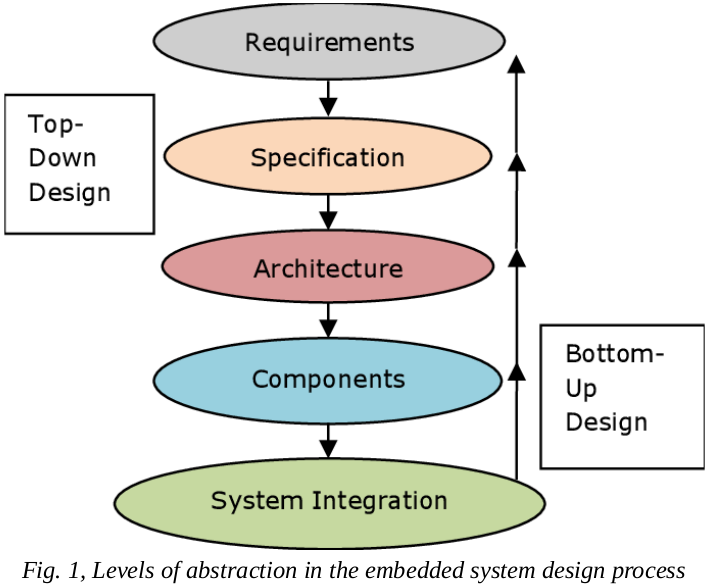
Embedded systems are computer systems with different peripherals to automate a task and control a procedure. Embedded systems are mostly based on microcontrollers (MCU), programmable electronic devices. In this project, a pre-designed PCB based on PIC MCU is provided. The PCB is a control panel for controlling a coffee grinder machine. There are two approached in embedded system design, this link.
Project Definition
There are different steps to design embedded systems:
- Analysis of Requirements: First we evaluated the available coffee grinder machines in the market, and then made a comparison to what exists and what we require. Next we provided the components for our controller panel (BOM). It is also necessary to say we have to direct our design to what we have in the warehouse.
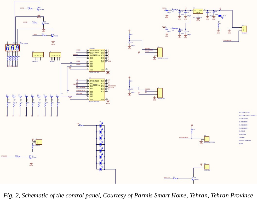
- Schematics: In this stage we have to design the arrangement of pieces of hardware of the system, including input/output preipherals, power supply, indicators, selection of a suitable MCU, and etc. Each electrical component must be drived based on its datasheet. For our case the following is the schematic of control panel:
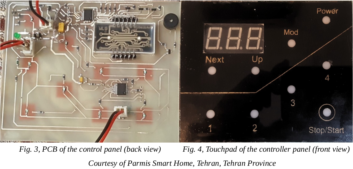
- PCB (Printed Circuit Board) and Prototype: According to the former step, component-level view of the electronic system, now we have to design a circuit board and test it to be free of error.
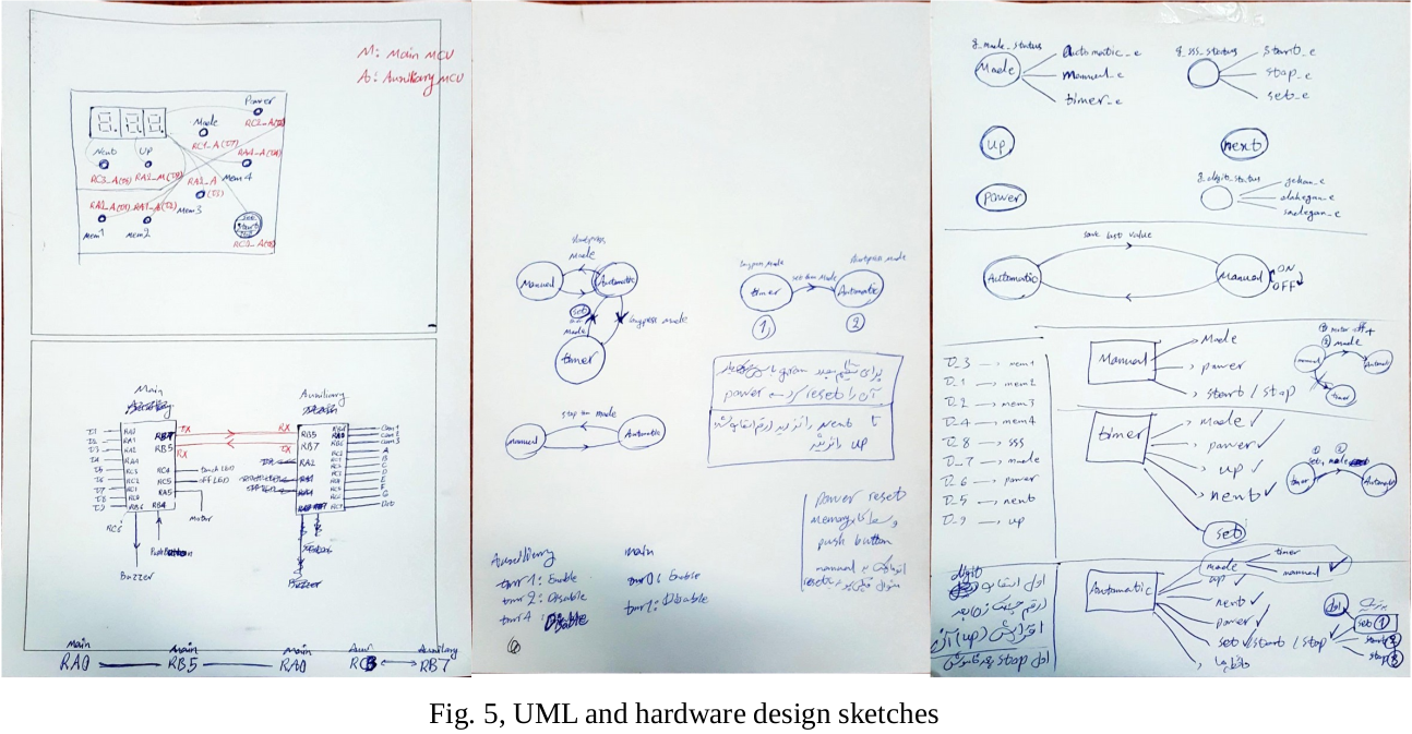
- Firmware Development: This was my main task to develop a programm for two PIC16F1829 MCU. The MCUs are in connection via USART. In this case, PIC16F1829 MCU did not have sufficient pins for our task and we were out of other models of PIC MCUs, so it was decided to deploy two of them. One of them were used for driving 3 digit 7 segments and buzzer, the other one for touch, mechanical keys, and the timers.
The controller panel consists of 9 touchpads, a buzzer, a mechanical key, a 3 digit 7-segment LED display, and a LED indicator. It has one touchpad for turn on/off the machine (Power), one touchpad for starting/stopping the process (Stop/Start), a touchpad for changing the digits (Next), a touchpad for changing value of selected digit (Up), a touchpad for changing the mode of control, Automatic, Manual, Timer, (Mode), and four of the touchpads (1-4) are dedicated to EEPROM to store differet settings/configurations.
The challenging part of developing the firmware was distribution of tasks between the two MCUs, and having a continuouse reliable transmission. In addition to that, callibration of sensitivity of touchpad sensors was arduous.
In the following there are some of my UML-like diagrams before starting the development of the firmware for this project that could help me to have a better top-down view for designing.
- Testing and Acceptance: After the firmware development different tests must be done to validate both functionality of the firmware and the circuit. Also some scenarios must be defined for unexpected situations which makes embedded design challenging.
Video
In the following I will show you the functionality of the controller panel:
Code
The source code (Firmware) is on my GitHub.